Objective
In this lab, I implemented orientation control on my robot with IMU data.
In this lab, I implemented orientation control on my robot with IMU data.
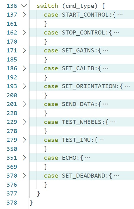
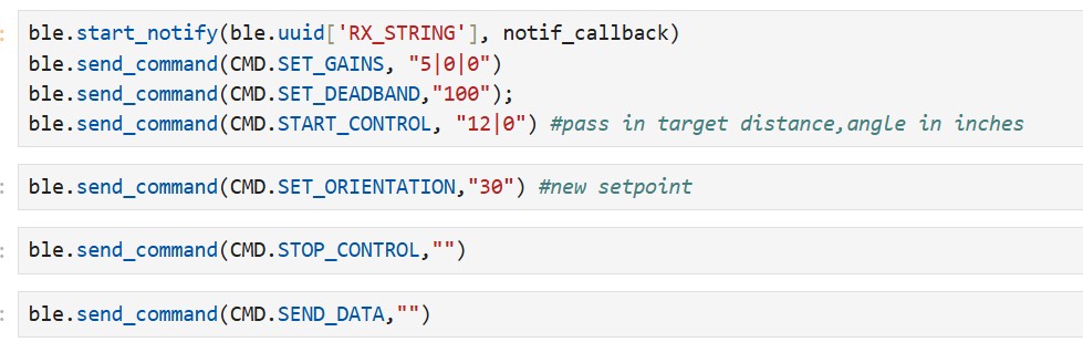
I use Bluetooth commands to start and stop control, with the main loop continuing execution as long as control_on remains true after the START_CONTROL case statement. Below is my void loop(), where the control flag is implemented:
Additionally, I can modify gain values and setpoints over Bluetooth while the robot is running. This is crucial for potential future implementations of real-time path planning. These modifications are handled via case statements in Arduino.
In Lab 2, I observed that raw accelerometer data is noisy, while gyroscope-based orientation data drifts due to digital integration. Previously, I used low-pass and complementary filters to mitigate these issues. To improve accuracy, I utilized the onboard DMP to read quaternion data and compute Euler angles. I enabled this by uncommenting line #29 in the IMU C header file. I also used example code to implement a `get_IMU()` function that updates the yaw value.
I ran my `TEST_IMU` command to collect 3 seconds worth of IMU data; I found that with DMP enabled, the IMU samples at roughly 80Hz, which is much slower than the speed at which the main loop executes. To handle this, I added an `else` statement to retain the previous yaw value if no new data is available.
Each iteration of the main loop computes control values and sends PWM signals to the motors via the control_orient_PID function:
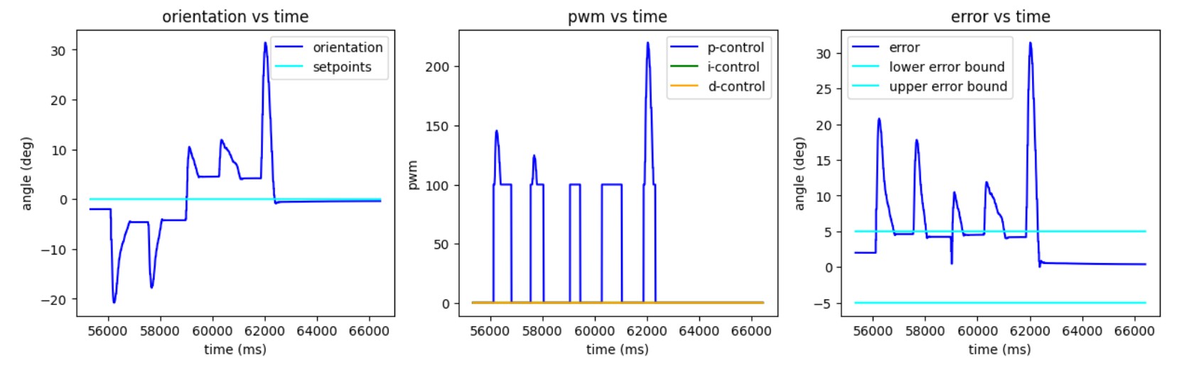
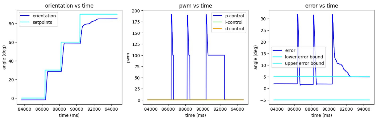
Currently, I use an error band of ±5 degrees, which I plan to make adjustable via Bluetooth. I implemented a `compensator` function that enforces a deadband of 100 and caps the PWM signal at 255. The higher deadband in this lab accounts for increased wheel resistance when turning. Through testing, I found that taping the wheels improves the robot's response by reducing traction.
I implemented a simple P-controller with a gain of 6. The integral term is negligible, so I decided not to include it. Implementing derivative control would be complicated. Since part of the orientation computation already involves integrating gyroscope data, taking the derivative of this data could introduce additional error, making it preferable to read raw gyroscope data directly. However, as seen in Lab 2, raw gyroscope data drifts significantly. My derivative control term from Lab 5 was also very noisy, requiring a low-pass filter for a clean signal. I decided that the benefits of a derivative controller were limited and opted for a P-controller.
Currently, the robot can control its orientation while stationary. However, future implementations will require orientation control while moving forward or backward. Instead of turning by driving one set of wheels forward and the other backward, I will adjust the PWM signal asymmetrically—e.g., increasing left-wheel PWM for right turns. To accommodate this, I can retain my current structure with minor modifications to compute_orient_PID and compute_linear_PID. I plan to introduce two global variables, left_pwm and right_pwm, to adjust motor output accordingly. Alternatively, I may combine orientation and linear control into a single function and conduct testing to determine which approach is easier to debug. Additionally, I will need to modify the orientation controller gains, as turning while in motion will be easier than turning from rest.
This lab was useful for getting familiar with using the IMU for orientation control.