Objective
This lab focuses on gaining experience with PID control.
This lab focuses on gaining experience with PID control.
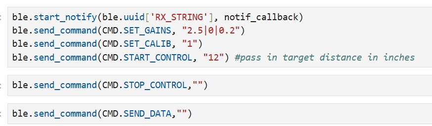
I implemented several BLE commands to make debugging and transmitting data over Bluetooth easier. My SET_GAINS command changes control gains without reprogramming the Artemis. My START_CONTROL and STOP_CONTROL commands raise flags that the robot continuously checks for; this allows me to start/stop the robot without having to “chase it down”.
Similar to previous labs, I let the robot continuously measure data in its loop() function and store it in arrays. After a run, I use my send_data command to transmit the stored data to my laptop.
In each iteration of the loop() function, my robot measures data and computes new PID values using a compute_PID() function I implemented.
The compute_PID function is shown below. [I forgot to upload this code snippet when the lab report was due. I understand that points will probably still be taken off, but I did want to clarify that I implemented this function before the lab was due.]
I set my PID gains to keep the PWM signal between 40 (the deadband from my previous lab) and 255 (the upper limit). Testing was done 6 feet from a wall, meaning the maximum error was 60 inches. This limited the maximum possible P-gain to 4.25. Initially, I used a P-controller with Kp = 2.9, but it resulted in over 10% overshoot, which I found unacceptable.
After tuning, I made several observations: a large proportional term causes overshoot, the derivative term is extremely noisy, and the integral term has little effect unless its gain is large.
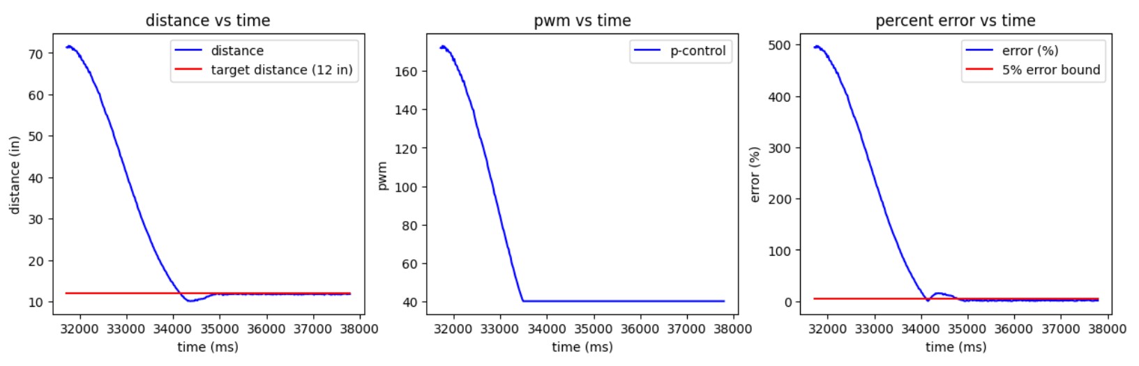
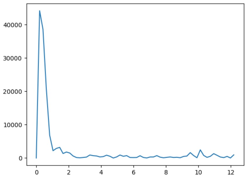
I implemented a low-pass filter for derivative control. By performing a DFT on a sample of derivative data, I determined a cutoff frequency of ~1.5–2 Hz. The two best-performing controllers were a PID controller with Kp = 2.5, Ki = 1, and Kd = 0.1, and a PD controller with Kp = 2.5, Ki = 0, and Kd = 0.2.
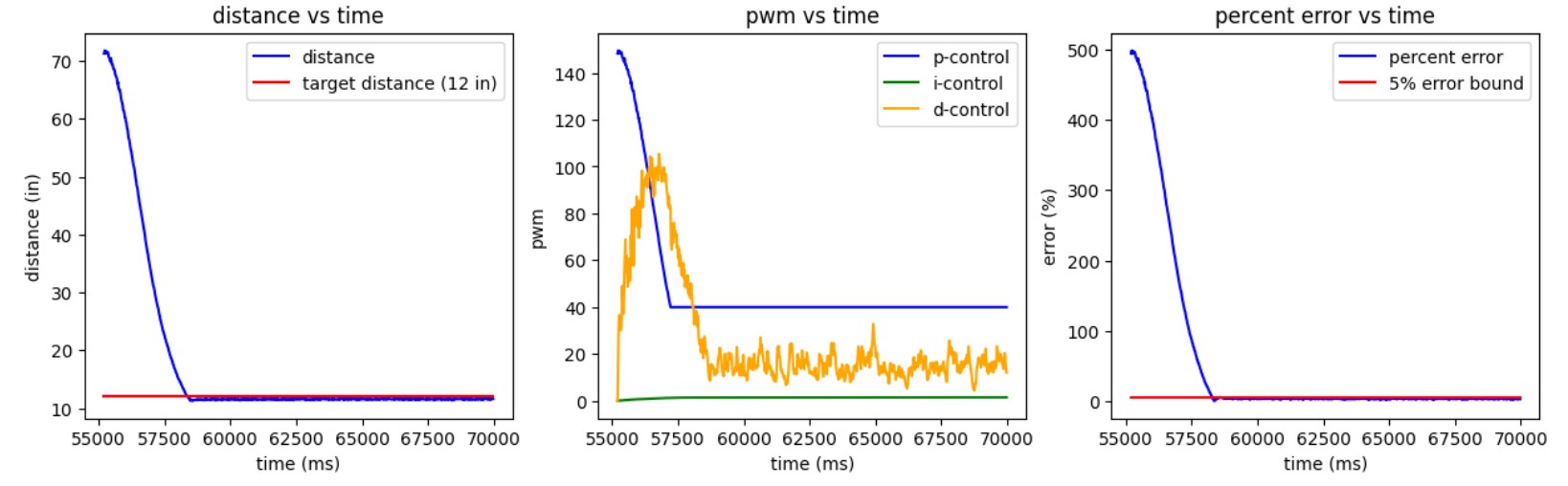
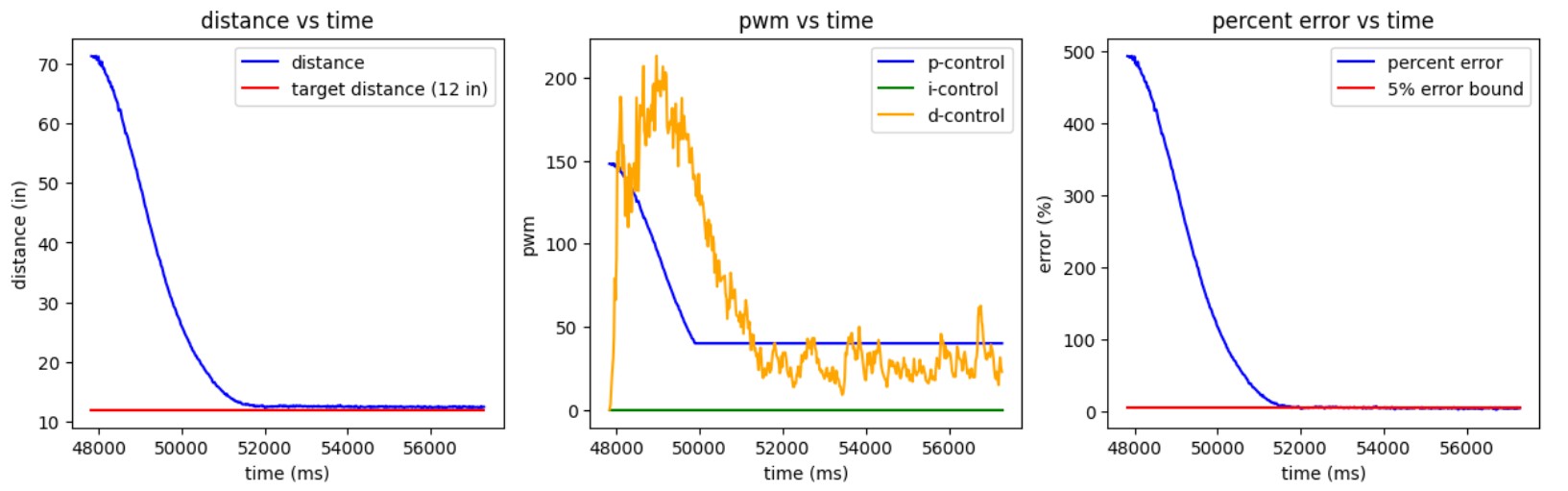
I liked these controllers because they had minimal overshoot and very low steady-state error. However, the robot moves slowly at 0.69 m/s, so I plan to tune it further for higher speed. Additionally, I only tested one starting distance—longer ranges may require adjustments. Moving forward, I may use only the PD controller to avoid integral wind-up.
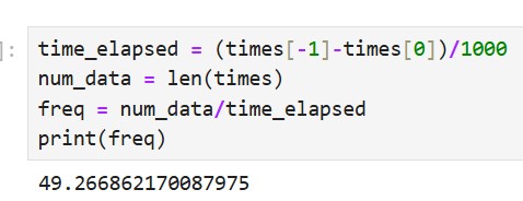
I used the ToF’s short-range mode; according to the datasheet, the ToF’s short-range mode performs best under ambient light conditions. Since the robot operates in such conditions, this was the optimal choice. To maximize sampling speed, I set the timing budget to 20 ms, the lower limit, allowing the sensor to sample at 50 Hz. I verified this rate with the data I collected.
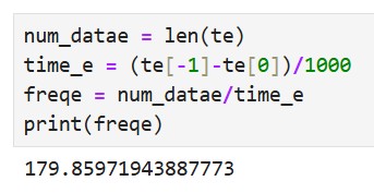
To speed up the loop, I moved my PID computation out of the if-block that checks if ToF data is ready. To compensate for loss of data, I extrapolated distance values using the following function:
I tested the extrapolation on a simple P-controller.
I was able to sample at a much higher rate, 180Hz, as shown below:
I worked with Rachel Arena on this lab.