Objective
This lab focuses on implementing open-loop control, enabling the car to follow a pre-programmed trajectory using the Artemis board and dual motor drivers.
This lab focuses on implementing open-loop control, enabling the car to follow a pre-programmed trajectory using the Artemis board and dual motor drivers.
The hardware will be wired as follows:
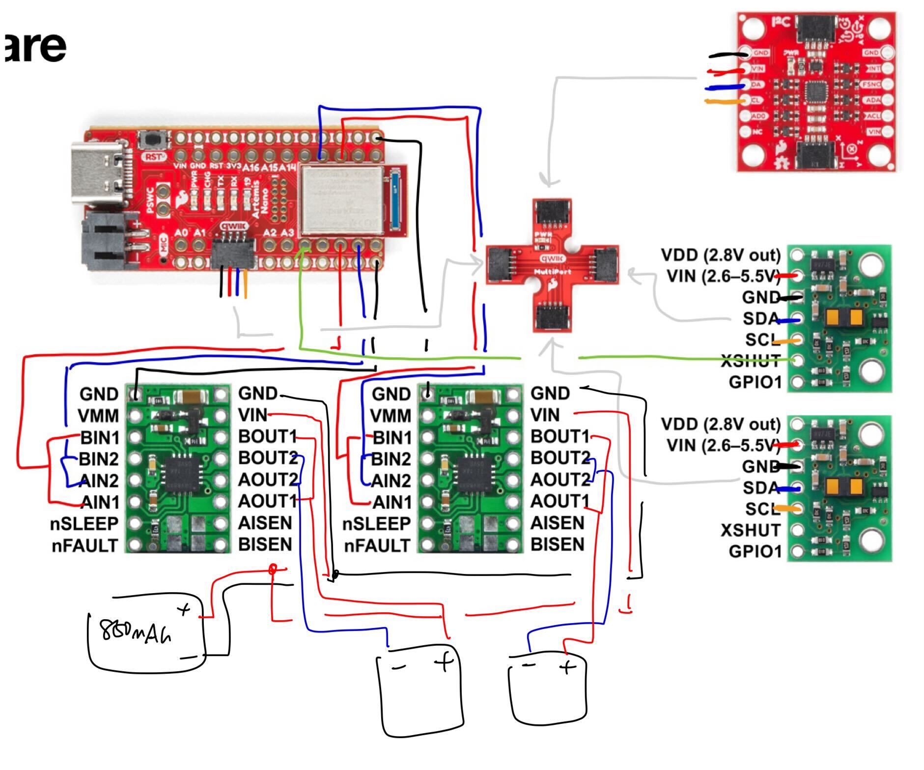
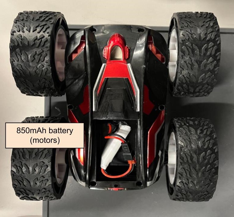
Pins 6, 7, 11, and 12 are suitable for the motor drivers because they are PWM-capable. The Artemis and motor drivers are powered from separate batteries, as the motor drivers will draw more current.
I validated the motor drivers using a power supply, probing them with an oscilloscope to confirm PWM signal reception. The supply voltage was set to 3.7 (equal to the battery’s nominal voltage) with a 2A current limit based on the datasheet specifications.
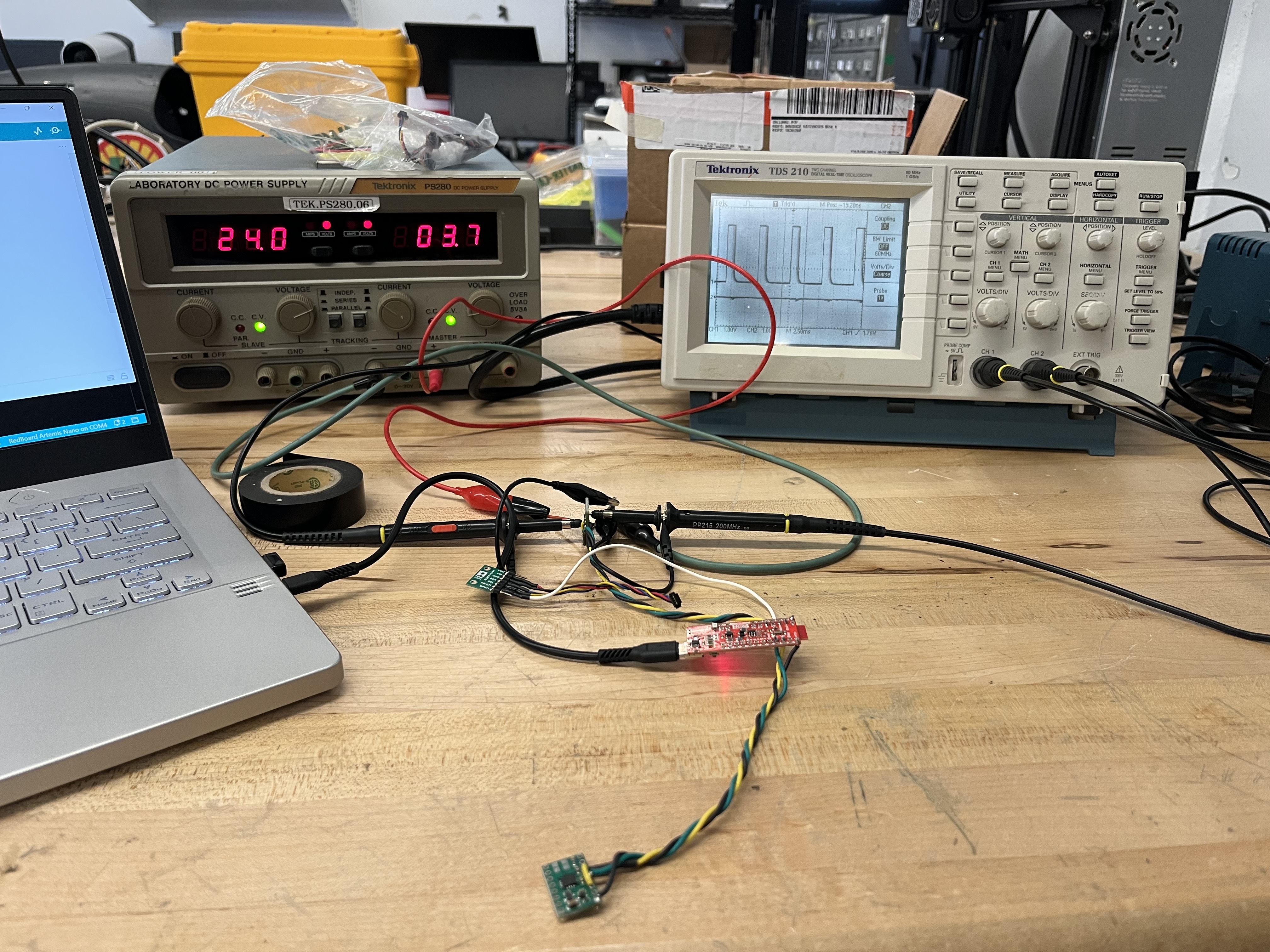
I sent the following signal, which was inspired by Nila Narayan’s lab report from last year. The duty cycle is varied to validate the motor driver’s range:
I then tested both motor drivers at the same time. As seen on the oscilloscope, a PWM signal is successfully being sent to both motor drivers.
Next, I soldered the drivers to the motors. I tested each motor separately, first on power supply then on battery.
After validating individual motors, I connected them in parallel and powered them both with the battery.
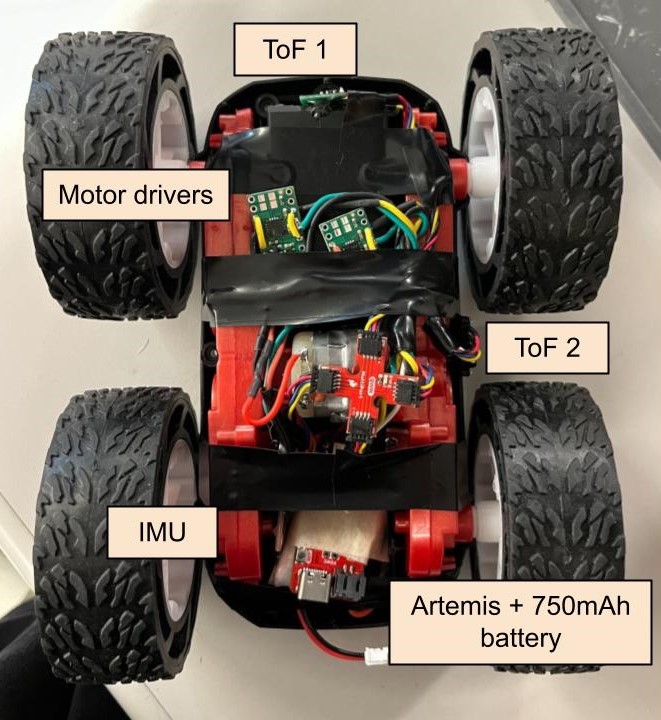
At this point, I mounted all hardware in the car. To reduce EMI, I kept my power lines short and twisted my cables. I kept the batteries and the Artemis easily accessible for charging and debugging purposes. I glued the ToF sensors to the front and sides of the car and placed the IMU in the same compartment as the Artemis.
After, I was ready to run the car on the ground.
I did some trial and error to find the lowest PWM value the motors could have to overcome rolling resistance. At a duty cycle of 30%, the robot was “crawling”. It rolled quite smoothly at 40.
I then tested if the car could move in a straight line for 6 feet. When the duty cycle was set to 40, it was able to do so quite easily.
There was some slight drift when I increased the duty cycle to 100.
Since drift wasn’t too dramatic, I set the calibration factor to 1.1. This allowed the car to move in a straight line for more than 6 feet: The code and video are shown below:
To demonstrate open-loop control, I pre-programmed the robot to perform the following sequence of movements:
As seen in the video, the robot can move forwards, backwards, and turn in either direction.
It was exciting to see the robot come to life in lab 4. Testing with different PWM values and trajectories was very useful for getting a feel of the robot's dynamics.
I referenced Nila Narayan and Bhadra Bejoy's websites for this lab.