Objective
The goal of this lab is to implement planning and localization on the robot so that it can navigate through a set of waypoints in the environment.
The goal of this lab is to implement planning and localization on the robot so that it can navigate through a set of waypoints in the environment.
I used Kelvin's robot for labs 8-11. During ECE Robotics Day I revived my robot, but realized that it only worked if I commented out all TOF sensor code. Also, when I used Kelvin's robot my front and side TOF sensors were always flipped. I suspected the two issues were related; turns out I pulled the XSHUT low when it was supposed to be high, and changed the I2C address of the wrong sensor. I fixed the boot-up sequence and my robot now works as expected.
I’ll be relying heavily on my linear and orientation PID controllers, which have been working well so far. The linear control relies heavily on accurate time-of-flight (TOF) data. I took inspiration from Bhadra Bejoy’s report from 2023; Bhadra’s robot only moved in 90-degree increments so that a TOF sensor was always facing a wall directly. This strategy helps maintain accurate readings, as TOF sensors perform best when measuring distance to flat surfaces head-on.
From Lab 3, I know the TOF sensors have a limited range of about 1.5 meters, which is less than the lab’s dimensions. To ensure accurate readings, I moved the side TOF sensor to the back of the robot and now track distance traveled instead of distance remaining. This lets me use either the front or back sensor based on which is closer to the wall.
To test and tune the robot’s PID control, I hard-coded the trajectories between waypoints and sent them to the robot as orientation and position control commands.
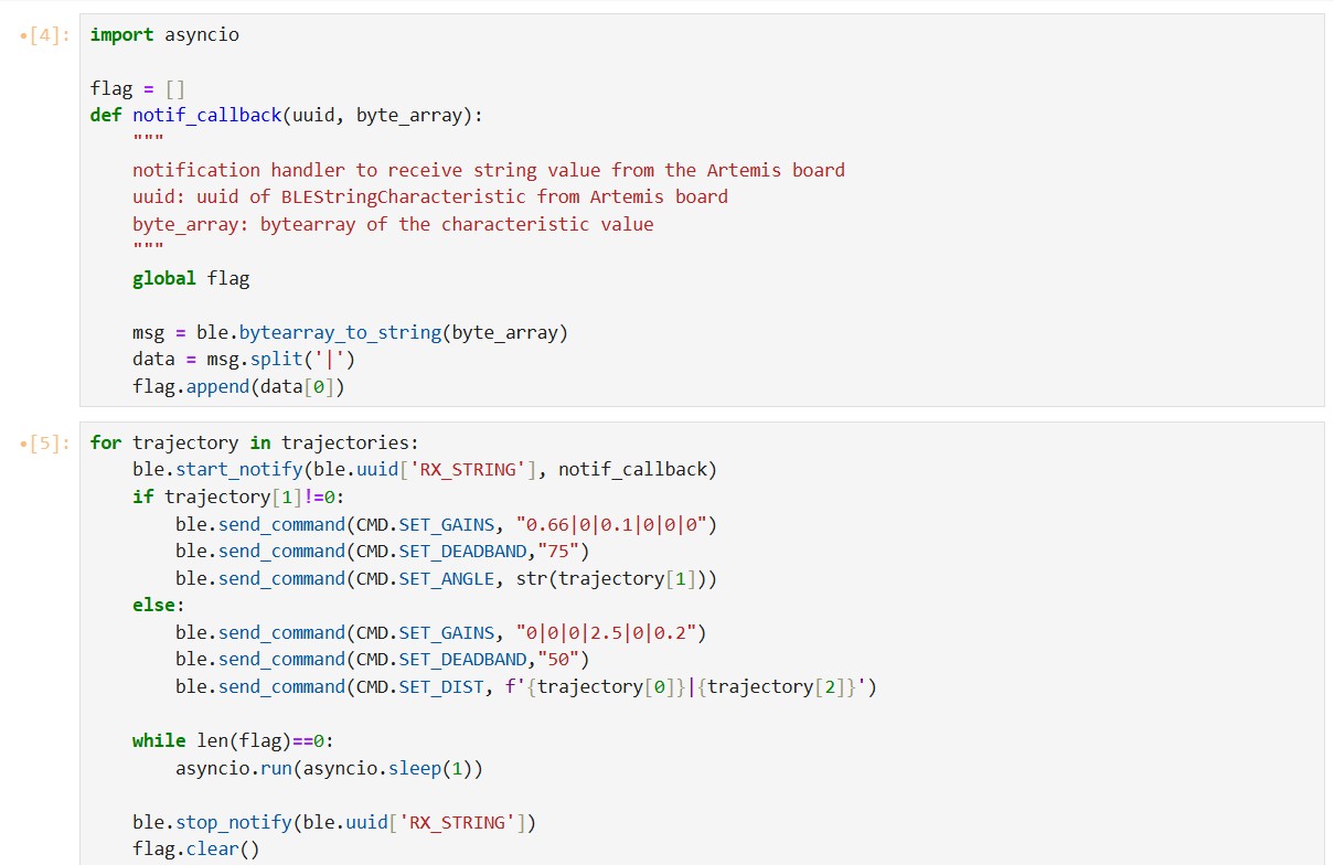
In Arduino, I use pointers to reference the front and back TOF sensor objects, making it easy to switch between them as needed. The SET_DIST command gives the robot its trajectory and tells it which TOF sensor to use. The function get_TOF() will store distance data from the chosen sensor in `dist`, which is used for linear PID computations.
My main control loop is shown below:
My robot made it through three waypoints before it went off-course. At the third waypoint, the robot does an unexpected -270 degree turn before starting its 90 degree clockwise turn. The robot proceeds to execute the remaining trajectories in the wrong direction. I suspect I didn't reset the IMU’s DMP properly.
In terms of physically testing the robot, this was all I could get done before I left for summer.
After fixing PID control, the next step would've been to use localization to correct the robot's trajectory if it goes off-course.
The localization results from lab 11 were terrible; after modifying the code it improved slightly but the robot overshoots by 20 degrees at the end of each observation loop. The polar plot of the recorded data indicates that the last measurement was taken at 360 degrees, which means that the yaw angle recorded doesn’t correspond to the yaw value at which the measurements are taken. I suspect this is because the yaw value is updated and stored in the get_IMU() function before both PID computations and TOF measurements are made.
Here is my updated observation loop, which I have placed inside of the `ON_AXIS_TURN` case statement instead of void loop():
Similarly to the odometry model, I split up the robot’s trajectory into 3 parts including 2 rotations and a translation. The robot will first rotate back to 0 degrees. Next, it will rotate to the angle between the current coordinate and the next coordinate. Then, it will travel in a straight line towards the next point. I decided it wasn’t necessary to localize at every point; the robots will localize at (1,-1), (5,-3), and (0,3). At those points, the TOF sensors are close to walls so it's easier for the robot to correct its drift. I used the Bayes filter code provided in previous labs as a base:
This time, instead of hard-coding which TOF sensor to use, I implemented a function `decide_TOF` that compares the standard deviation of 20 measurements from each sensor, and chooses the sensor that has the lower standard deviation. (This method was derived from Lab 3 results; measurement data has high stdev if the sensor is measuring out of range.)
Unfortunately my flight was booked for 5/13 and I spent the entire day travelling. I think I would need to take a closer look at the Python code and modify some of the Lab 11 base code in order for it to run properly.
It was unfortunate that I couldn't get this lab done in time. I really enjoyed this course and learned a lot from it; maybe taking it in tandem with heavy extracurriculars and other heinous classes wasn't the best time management decision on my part.
I referenced Bhadra Bejoy and Nila Narayan's websites from last year.